Electrical Safety Standards have progressed over the last century into highly sophisticated systems that include all main parts of a safe installation, including Earthing Systems.
For the measures to be applied in Low-voltage (LV) Electrical Installations, the reference standard IEC 60364 is employed.
There are three different ways you can ground the distribution system; TN, TT and IT grounding system as per the IEC 60364 standard.
The TN system is divided into three types: TN-C, TN-S, and TN-C-S.
What do TN, TT, and IT grounding system mean?
Before we start understanding the working principle of each system, let us first go through what each letter indicates.
What is the meaning of the letters T, I, N, C, and S in the grounding system?
‘T’ means direct connection to the earth. Terre is the French word that means ‘Earth’.
‘I’ – Isolated
‘N’ – Neutral
‘S’ – Separate
‘C’ – Combined
- The first letter denotes the power system’s connection to the earth.
The letter ‘T’, indicates that the source’s neutral point (star-connected winding of transformer) is solidly attached to the earth.
The letter ‘I’ denotes that the star point and the winding are designed and constructed to be separated from Earth.
- The second letter denotes the installation’s exposed-conductive parts’ connection to the ground.
There are two primary methods for earthing frames, cubicles, panels, and other similar items. T and N are the letters.
The letter N is subdivided into S and C, yielding NS and NC, as well as the composite NCS.
T indicates that the consumer has earthed solidly regardless of the source earthing method.
N indicates that a low-impedance conductor is taken from the source’s earth connection and transmitted directly to the consumer to earth the consumer’s equipment.
Working principle of TN, TT, and IT grounding system
After knowing the meaning of each letter, now let me tell you the working principle of each combination.
TN Grounding System
One point of the distribution system in TN networks is directly connected to the ground. The PE conductor connects each installation in the system to this common grounding point. There are three types of TN networks.
TN-S Grounding System
The neutral and protective conductor PE are separate and that is what the letter ‘S’ signifies. Take a look at the below figure.

TN-C Grounding System
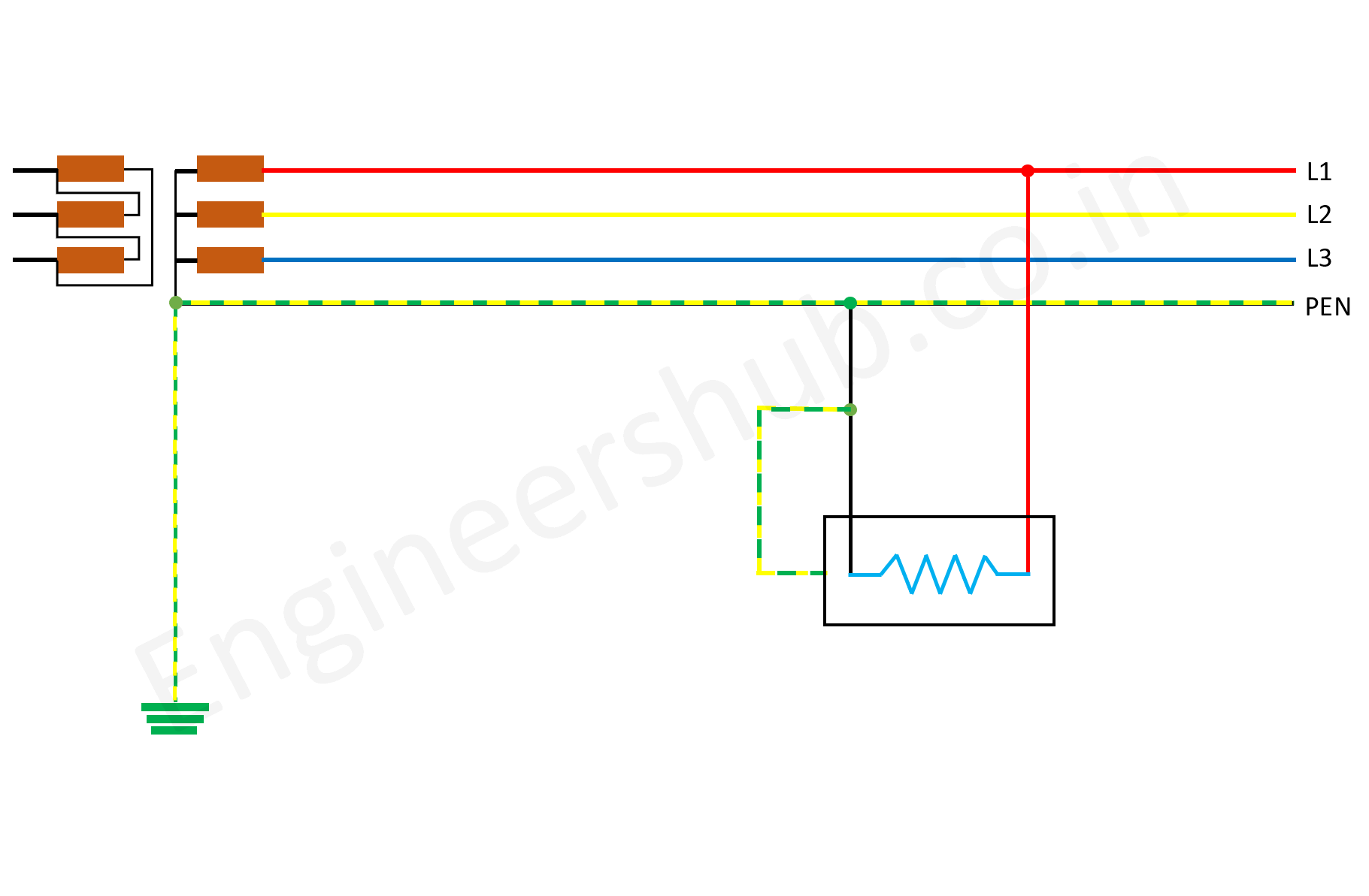
PEN is a conductor that combines the neutral and protective characteristics in this type of grounding arrangement.

TN-C-S Grounding System
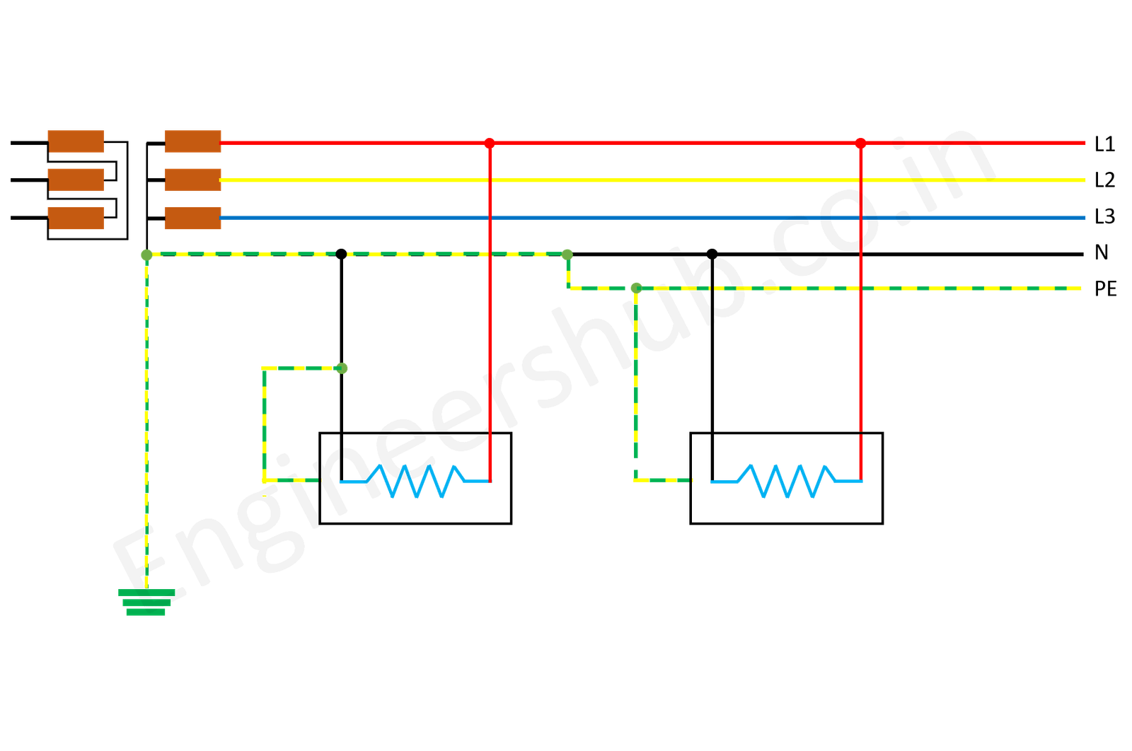
The neutral and protective functions are partially merged into a single PEN conductor and partially the PE + N functions are somewhat separated.

TT Grounding System
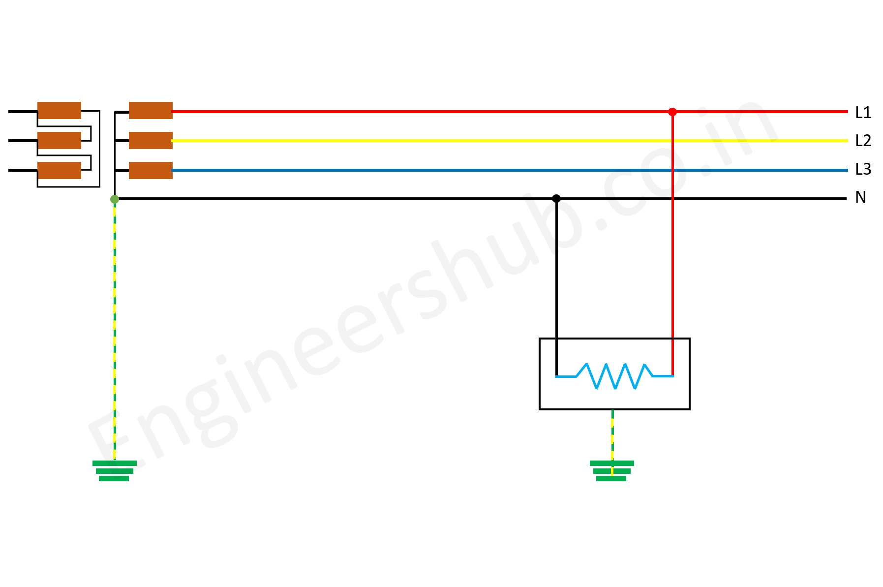
The neutral and exposed-conductive components of TT systems are connected to separate earth electrodes and hence they are electrically independent of each other.

The neutral is generally distributed in these types of electrical facilities, and its job is to make the phase voltage (e.g., 230 V) available for supplying to single-phase loads in civil installations.
IT Grounding System
The neutral is not directly connected to the earth electrode, which means the neutral is kept isolated from the earth. However, the exposed conductive parts may be connected to the earth via high-value impedance. The exposed conductive elements are connected to an independent earth electrode, either individually or in groups.

Conclusion
TN distribution system is usually suitable for the user having their transformer (MV type) substations. And hence, big industries prefer to use the TN system.
TT system is suitable for small LV supplies. In this case, it is the user’s responsibility to protect against indirect contact.
IT system is best for the industries having service continuity must. Chemical and petrochemical are such industries.
So which distribution system are you going to select for your plant? Comment me in the section below.


Living in Norway, one of the few countries using IT-power distribution. In IT network in Norway I have never seen a N-conductor! Loads are connected between say L1 and L2 receiving 230V. Up til about 1995 all outkets in dry rooms had no earth connector. Today all outlets are with an earth connector connected to a earthing electrode in the ground, often a copper wire burried under the basement. The senter point in generators or local distribution transformers are isolated from earth, but with a overvoltage barrier which will brace and earth the senterpoint in case of a lightning stroke.
I find the illustration here regarding IT to be wrong, at least in Norway.
I am very much thankful to you Kjell Gjare. There was a graphical error in illustration.
I have removed it.
The standards are the same in all over the world.
Thanks for the information, help to understand this type of connections
Thank you