You may need to check the insulation resistance of a motor in mainly two different conditions.
Motors running continuously require insulation checks periodically. Look at the following graph. You can see the motor insulation deterioration.

At point ‘A’ the motor is put on service.
Due to aging, contamination, temperature, moisture, etc. the motor insulation resistance decreases as indicated by point ‘B’. However, you can still use the motor.
The point ‘C’ indicates the motor insulation failure. In this case, you can no longer continue to use the motor. Either you have to replace it with a new one or rewind the old motor.
The point ‘D’ indicates the condition of insulation of the motor after rewinding.
Another situation is, let’s say you have a new motor, kept idle for a long time – say more than 2 months, then you must check its insulation resistance before you put the motor for operation.
In this article, I would give you step-by-step guidance on – how to check insulation resistance of motor with illustrations.
You must have an insulation resistance tester to check the insulation.
Safety Cautions!
The insulation tester can discharge any residual test voltage. So, leave the leads connected when you stop the test.
Do not use the tester in an explosive atmosphere.
How to check insulation resistance of motor?
Step 1: Disconnect the power cables of the motor. Also, the leads that are connected in star or delta.
The insulation tester uses higher DC voltage. Performing insulation testing can damage electronics like motor drives, PLCs, transmitters, sensors, etc. So, always remove the power cable connected to the motor.

Checking Insulation resistance between ground and each winding of the motor
Step 2: Connect the insulation resistance tester to the motor.
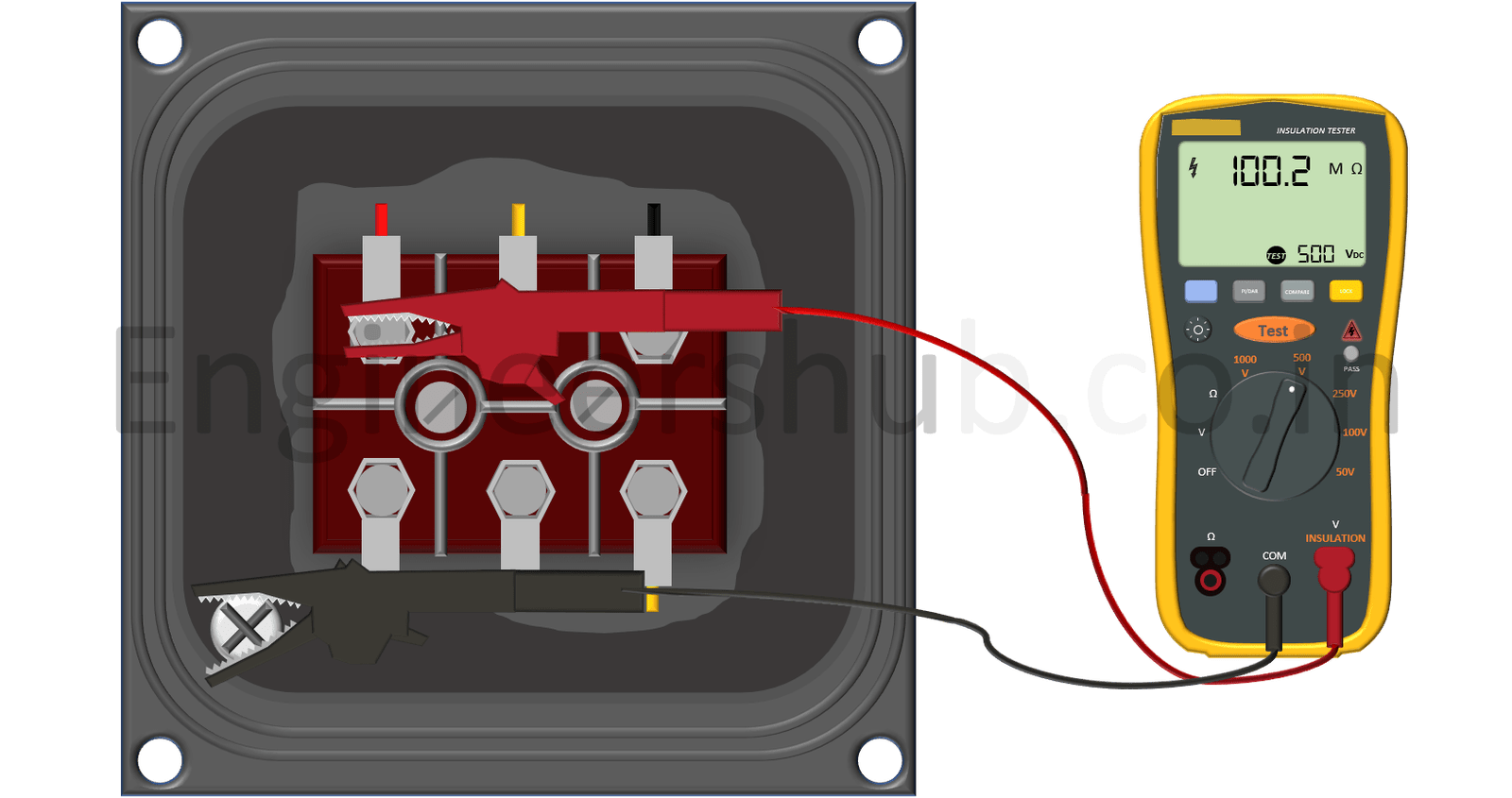
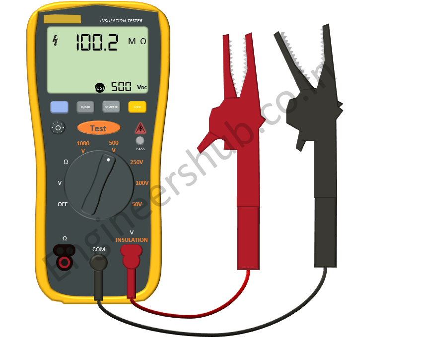
Plug one end of the black lead of the insulation tester to the common terminal of the meter and other end to the body of the motor or a good ground terminal.
The mounting bolts are the best place to connect. Remove the paint applied to mounting bolts.
The layer of paint acts as an insulation. You may get an erroneous reading if you do not remove the paint.
Standard motor manufacturers provide a separate terminal for grounding inside the motor terminal box. You can connect the black lead there also.
Plug one end of the red lead to the Voltage / insulation terminal and another to the winding U1. Refer to the below image.

Step 3: Select the suitable DC voltage.
Follow the below table for selecting suitable DC voltage as per IEEE 43-2013 standard.

Remember that if the selected test voltage is too high, the applied test voltage may even damage the insulation. Better to go with the IEEE’s recommendations.
Step 4: Test the insulation resistance of the motor and note down the readings of insulation resistance.
Press the test button provided on the insulation tester.

You must apply the DC voltage for 1 min as recommended by IEEE-43 and then you should note down the readings of insulation resistance.
Step 5: Repeat the test for all three windings and note down the readings.

Checking Insulation resistance between each winding of the motor
Step 6: Check insulation resistance between each winding of the motor.
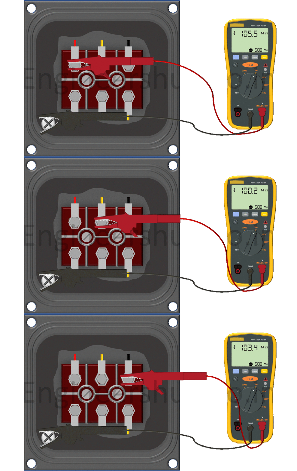
Simply put the black lead on one winding say U1 and red lead to another winding say V1 of the motor. Likewise, check insulation between W1V1 and U1W1. Look at the below image.

Repeat the test between each windings and note down the readings.
Step 7: Evaluating the readings taken.
Compare the readings with the motor’s test report given by the manufacturer.
The organization name NETA (InterNational Electrical Testing Association) provides minimum insulation values for various voltage ratings shown in the below table.

You can use these values in absence of the manufacturer’s data.
Let’s say – your equipment which you have checked has 600 V as rated voltage. Then the reading should be nearby 100 Mega ohms as per the above table.
If you have got readings like 2 Megaohms, 5 megaohms then you may need to replace the motor.
Wrapping Up
In general, most of the motors installed inside the plant are working continuously.
Hence, they develop insulation weaknesses.
Periodic checks are a must. The frequency of periodic checks varies from every 3 months to 12 months.
Establish a test schedule for continuously working motors. You can avoid surprise breakdown maintenance.
Reference:
- IEEE 43-2013 – Recommended Practice for Testing Insulation Resistance of
Electric Machinery. - NETA Maintenance Testing Specification 2019.
- NETA Apparatus Testing Specification 2021.
Related Articles


