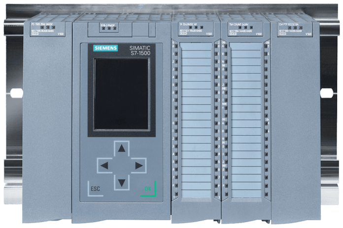
PLCs, or programmable logic controllers, are essential parts of industrial automation and are in charge of carrying out a variety of duties in production processes.
Any PLC If you are working on PLCs, you may need to select the hardware components of the PLC.
In this article, I will explain to you the essential components of the PLC system.
Components of PLC System
The PLC system consists of a –
- DIN Rail / Rack
- Power Supply
- CPU (Central Processing Unit)
- Digital I/O Module
- Analog I/O Module
- Function Module
- Communication Processor Module

Now let us understand each of these components.
1. DIN Rail / Rack

The DIN rail is used to mount components like power supply, CPU, I/O modules, functional modules, etc.
The DIN rail is standardized. As per IEC 60715, the size of the DIN rail is the same throughout the world.
You can also mount other components like relays and connectors.

The rack is different from the DIN rail. Rack serves two main purposes. The components of the modular PLC system like the CPU, Power Supply, I/O modules, etc. are mounted on the Rack.
Rack provides both mechanical connections between these components and also the electrical connections.
It provides communication signals and distributes power to these modules.
2. Power Supply

The function of the power supply is to provide regulated 24 VDC / 10 VDC / 5 VDC / power supply to the CPU, I/O modules, etc.
It converts 230 VAC or 120 VAC (USA) into 24VDC. This 24VDC is further distributed to the CPU, I/O modules, etc. either through wire or the Rack of the PLC.
3. CPU (Central Processing Unit)

CPU can be divided into two sections. One is the CPU section and memory section.
The CPU executes the user program. It also helps users to establish communication between computers/laptops and the PLC. By establishing the communication between the PLC and computer it becomes easy for the user to upload or download the user program.
The memory section stores the user program. It also stores the tag names of the field devices, memory addresses, and the values of timers and counters.
4. Digital Input / Output Modules

The field devices like proximity sensors, limit switches, etc. give input discrete signals to PLC. These input field devices are connected to digital input modules.
The digital input modules protect the CPU from external electrical noise signals present on the field by isolating the voltage potentials.
However, in standalone PLCs, you can still connect these discrete field devices directly to the CPU but are limited to a few numbers. If you want to expand the number of inputs or outputs you can connect digital input modules or output modules separately to these standalone PLCs as well.
You cannot turn ON field output devices by sending 0s and 1s. Take the example of relay. A relay requires voltage potential to get energized. The voltage potential could be either 24VDC, 12VDC, etc.

The digital output module decodes the computer-level machine language into suitable voltage potential to either turn ON or turn OFF the field discrete devices.
5. Analog Input/output Modules

The field analog input devices like pressure transmitters, temperature transmitters, etc. send an electrical signal to PLC in either 4-20mA or 0-10VDC.
The PLC CPU cannot understand the electrical signal sent by these devices. This analog input module converts analog signal to digital signal with the help of an ADC converter so that the CPU can understand.
The analog output modules have DAC i.e., digital to analog converter which converts computer-level language into a suitable analog signal for analog field output devices like control valves.
6. Function Modules

Function modules can readily be connected to high-speed counter modules, PID modules, and weighing modules. Additionally, using function module cards, PID, CNC, and position controllers can connect to PLCs.
7. Communication Processor Module

The communication processor is an optional module. It can be applied to give communication protocols a second communication port.
It serves as a networking communication tool for PLCs or numerous processors. Data is also sent between PLC, SCADA, HMI, and other systems via CP.
Conclusion
Anyone working in industrial automation must have a thorough understanding of PLC systems. Every component is essential to the system’s overall operation. PLC systems continue to develop as technology does, adding increasingly complex features and capacities to suit the needs of contemporary production processes.
Image Source
- Siemens.com (“© Siemens AG 2023, All rights reserved”)
Other PLC Articles to Read
- Become a PLC Pro: The Ultimate Guide to Finding the Best PLC Training Courses
- Basics of Ladder Logic
- What is PLC (Programmable Logic Controller)?
- History of the PLC (Programmable Logic Controller)


